Please help bring my beautiful Apple G5 back to life.
[maxbutton id=”4″]
Are you having problems with your Apple iMac G5 17 and 20 inch consumer, university, or student models? Does your iMac turn off by itself? Are you seeing strange graphics on the video screen? Is it to the point where it doesn’t even turn on anymore? Is it running hot and the fans sound like a vacuum cleaner?
Apple iMac G5 Information
Well folks, here is one of the problems with many of the Apple power supplies manufactured for their iMac G5, 17 and 20 inch series computers. But fear not, I have put a “How to Fix Series” together on how to fix an iMac G5 power supply and mother board. Power supply information is located right here in this article. I would also suggest reading the latest article on Fat Caps and Ripple Current to have a better understanding of what is happening with Bad Caps inside these Apple iMac G5 power supplies and logic cards.
Also, you can read and see how to fix the G5 mother board over here.
If your Apple iMac G5 power supply doesn’t match up exactly to what you see pictured below, feel free to send me your pictures (inside and outside of the iMac MOBs and PSUs). I also have provided additional pictures for comparing which PSU capacitor kits are available for the various power supplies over at “Inside the Apple iMac“. You can also click the buy now buttons to purchase the power supply kits.
As a side note, if you need to get the data quickly (pictures, files, and programs) off the HD for your old Mac, and place it on your HD on the new Mac, read about the ›Apple iMac G5 Hard Drive Data Recovery. It is designed for those that want to recover the information from their hard drives on a dead PC or Mac. This HD device works really great for Apple iMac backups too!
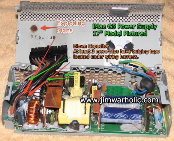
180W – Apple P/N 614-0293
Figure #1
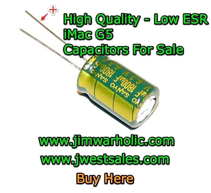
Updated 9/12/09: High Quality Low ESR capacitors, computer motherboard grade, 105ºC, 10mm X 16mm, now available for sale in kit form for the Apple iMac G5 computer MOBs and the PSUs.
The capacitor sizes, included in the MOB kits, are the actual original sizes of the capacitors on the motherboard; making your job much easier to replace them. They are the perfect fit for both diameter and height. Note: The PSU cap kits have been upgraded.
International shipping is available for many countries. If your country isn’t listed for a shipping destination, please let me know to add your country to the list. Please provide your full name (first and last name) when ordering capacitors. Read the Shipping for shipping and delivery information.
If you are interested in more than 10 MOB cap kits, please send me an email with a total amount of how many iMac G5 cap kits you are looking for, along with a note of which of the two different cap kit sets you are interested in. Note: Apple early model and late model iMac G5s with the PowerPC processor have different quantities of caps required on the MOB. Click the eCommerce link. Capacitor information is provided there. Verify what capacitors your Apple iMac needs, and bring your iMac G5 back to life today.
Send me an email with your questions, or special order requests. I now have all the power supply cap kits available. Feel free to contact me any time, with any questions. Take a look at the PSU cap kits that are available for purchase.
Just a brief update for those that have been out of the capacitor loop. About the time Apple was building their G5 line of personal computers, several Taiwanese electrolyte manufacturers began using a stolen electrolyte formula that was incomplete, and lacked key ingredients needed to produce a stable capacitor. The missing ingredients caused the electrolyte in the capacitors to break down, evaporate, leak out of the cap casings, caused overheating of the capacitors themselves under normal load conditions, and subsequently caused exploding poppers. Consequently the capacitors started bulging, overheating, and exploding in many of the power supplies and mother boards manufactured by Apple, Dell, Hewlett-Packard, and others which has been documented by numerous articles online. In fact, Dell took a “$300 million financial charge on its earnings to cover costs associated with the replacement of motherboards with faulty capacitors in some of its Optiplex workstations” in late 2005 early 2006. For those of you that are interested, I have documented a do-it-yourself repair procedure and an educational information manual on the Apple iMac G5 motherboards along with students’ user comments.
Note: Apple provided an iMac G5 Repair Extension Program for Video and Power Issues: See the frequently asked questions section at Apple about which models and serial numbers are/were covered. Howeve
r, in all likelihood (“As of December 15, 2008, this program is now closed.”), the iMac G5 Repair Extension Program has run out its course for most, if not all iMac G5 PowerPC owners. See Apple information on the power supply and the video and power issues documents. You can read the actual repair extension program text in the Apple iMac Mother Board article, exactly as it was in the original Apple documents. The program was available for certain iMac G5 PowerPC models that were sold between approximately September 2004 and June 2005 featuring 17-inch and 20-inch displays with 1.6GHz and 1.8GHz G5 processors. You may also go to any Apple Retail Store with a Genus Bar and have the Apple folks take a look at your iMac for you. Find the nearest Apple Retail Store – Genius Bar in your area, and even make an Genius Bar appointment online too. Apple provides technical support for your Mac, iPod, Apple TV, and iPhone at the Genius Bar too.
Identifying the Apple iMac Power Supply Problem or iMac G5 Motherboard Problem
Apple provides a diagnostic guide for determining whether the problem is with the motherboard or the power supply. See the following link to the: iMac G5: Troubleshooting when your computer won’t turn on. Included in that Apple document are instructions of how to turn on an iMac with the back cover off. There are two small buttons located under the fan cover as displayed in the document. One button is the internal power button, and the other button is for resetting the System Management Unit (SMU) which is located right next to the internal power button. “Note: If you’re using an iMac G5 (Ambient Light Sensor) computer, your SMU was already reset when you unplugged and replugged the computer. You won’t see an SMU reset button to press, and that’s OK, as this action has already been done. (If you aren’t sure which iMac G5 model you have, click here for help.)” Source: Apple
Since, I feel that I have been somewhat of an online trailblazer on documenting the iMac issues and the Apple iMac G5 motherboard repairs project, I thought I would take the time to dive into another area that many of our readers have stated is also a big problem with the Apple G5 line of computers. That big issue has to do with the main power supply installed in the iMacs are dying and dropping like flies. From what I understand (though not confirmed) about the iMac PSUs, is there are at least several different power supplies used by Apple in their iMac G5 model lines. The part numbers are located on the back of the PSU case. This power supply is Apple P/N 614-0293 Rev. A 180W. The serial number has a barcode graph. The various models associated with this particular DIY repair document are for Apple: iMac G5 (20-Inch), iMac G5 (20-Inch iSight), iMac G5 (17-Inch), iMac G5 (17-Inch iSight), iMac G5 ALS (17-Inch), and iMac G5 ALS (20-Inch) consumer, university, and student models. See the Apple Power Supply, 17-inch Replacement Instructions for how to remove and install your power supply unit. If you have an Apple model with the ambient light sensor, pay particular attention to not breaking the wiring or the sensor that is mounted to the lower portion of the power supply when removing the PSU. Ok, that gets your power supply unit out. Now what?
There are several service repair or replacement options available for your iMac G5 power supply.
- Order a new power supply from Apple Parts & Services.
- Order a new PSU, rebuilt power supply, or have your PSU repaired from an outside source.
- Repair the power supply unit yourself.
Before I talk about option number three, I would like to point out that when you buy a used or new power supply from Apple or another vendor, you have no idea whether the capacitors that are used in this new or used PS are any better than the ones that were installed in your particular iMac. In all likelihood, the new or rebuilt PSU might not last either. I have heard stories of Apple Service replacing a person’s iMac power supply, and several months later having to do it again. With that being said, it seems obvious that you are taking a chance no matter what you do. By-the-way, the cost of a power supply for an iMac will likely set you back 150 to 200 buckaroos. To me, $150.00 or $200.00 seems like an awful lot of money to shell out for such a small power supply that might not last more than a few months. Capacitors actually get old just sitting on the shelf.
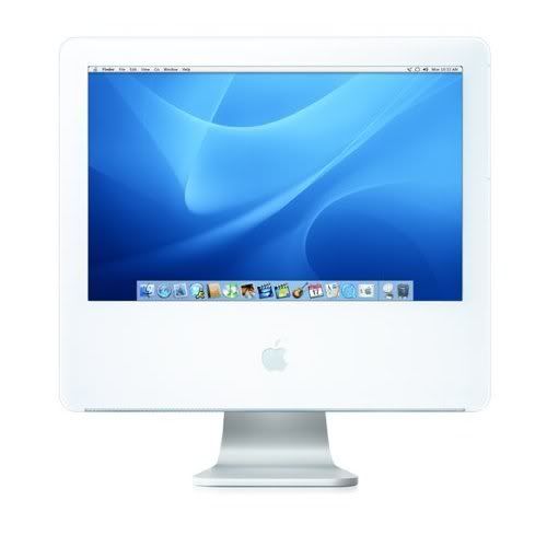
Figure #2
With many of my readers sharing their iMac G5 stories, both in the online comments section and sending emails to me documenting their problems they are having with their Apple iMacs, I thought it was prudent to take the next step and see if I could discover first hand what was going on in the field with these 17 inch iMacs. I already own an Apple iMac 20 inch model but I needed a 17 inch one for further investigative work. So, I went searching for a broken iMac G5 computer that I could get my hands on for a fair price. I didn’t want to spend a ton of money on a broken Apple to do my research, but I needed to do some more engineering and technical failure analysis of the problems of iMacs not turning on because of mother board problems or a power supply situation. Many people kept telling me that they had an iMac G5 17 inch model computer with no physical signs of bad capacitors on the motherboard. I wanted to verify this for myself. I found an iMac G5 17 inch on Craigslist from a guy that felt he got ripped off by someone selling a supposedly good working iMac to him a short time back and then when he plugged it in, it didn’t work. He took it to the local Apple Genius Bar folks and they said he needed a new motherboard. So, after talking with the seller and asking him some questions about this particular iMac, we settled on a fair price, I met him in San Ramon, CA, and purchased it from him. In my opinion he was a straight shooter, and was nice enough to allow me to open the back cover up before I purchased it in order to make sure all the hardware was inside, i.e., hard drive, motherboard, power supply, fans, memory, cd/dvd SuperDrive. However, he had given away the keyboard, mouse, and the software to some friends. Oh well, keyboards and mice are not very expensive, and if I need Mac OS X software, I can purchase that too.
So, I get my new, broken, what an oxymoron, iMac G5 back to the office and I plug it in, push the power button, and it just sits there staring at me with a blank screen. Nothing powers up. Dead in the water. Dead on arrival. DOA, just what I wanted. Really! Yes, it was time to go to start my engineering class work. I opened the back of the computer once again and took a much closer inspection of the motherboard and the capacitors. Believe it or not, all the capacitors look good on the MOB, just like some of my readers have documented with their own stories in written emails I received from them. This is a completely different issue than what I saw on my iMac G5 20 inch motherboard problem with the bad capacitors on the MOB, with some caps just about ready to pop. All the capacitors on this motherboard looked completely intact, with no signs of swelling, bulging, or electrolytic juice leaking out anywhere to be seen on this 17 inch model.
The next step in my troubleshooting analysis probe was to remove the power supply and do the smell test. Yes, use your other senses other than eyesight when troubleshooting electronics or checking out other industrial equipment. The smell of burnt electronic components can sometimes be detected months and years later, even after a burnt component has been replaced. I placed the power supply up to my nose, and I thought I got a slight whiff of that unforgettable smell of burnt electronic components. Now, it was time for the 20/20 vision eyesight test.
Danger High Voltage Electrical Shock Warning!
This information is provided as a safety precaution and to be careful. A warning at this next stage of the technical analysis is warranted. Electronics, and power supplies in general have high power electronic circuits which can cause a body harm if you touch the wrong thing, even if unplugged. First off, make sure your power supply is not plugged into the AC power outlet. Note also that power supplies typically have a primary high voltage input side and a secondary low voltage(s) output side. The high voltage input side can have large filtering capacitors which can store an electrical charge (DC voltage potential) for a long time, even after a power supply is unplugged from the AC power outlet. Take the precautionary step, and discharge these primary capacitors (after it is unplugged from the AC power) with a screwdriver or place jumper wires across the leads prior to working on the PSU printed circuit board. If you have a different type of supply than what is shown here, with large cylinder capacitors standing up on the primary side, you will not be able to get to the leads on the bottom of the circuit board in order to discharge them. However, if a power supply is left off, unplugged for a period of time; certainly if it has been off and unplugged for an hour or two, the majority of the charge will have dissipated from the capacitors due to in circuit resistance and time.
The iMac G5 PSU case design, is one by which Apple’s engineers designed their power supply units with security torx fasteners (screws) attaching the metal cover housing to prevent unauthorized disassembly, and also I am sure to prevent anyone from getting hurt. I do not own one of these security torx drivers, as I suspect most people can say they don’t have one in their tool box either. I was having an email conversation over the past week with a physics professor at a university. He mentioned he has ten 1.6GHz 17″ G5 iMacs at the university, four of which have already collapsed completely. He was also the first to mention to me, about the security torx key being required to open the PS cases.
In this case no problem on the mother board, but big trouble in the power supply (lots of caps in trouble, one totally blown). One can see some of them through the power supply case, so you might want to take a look at yours.
Be careful of the two high capacity capacitors in the unit, they can be lethal. Ph.D., ARCS
I was able to unscrew the torx screws using a precision miniature screwdriver, and broke out the small internal security tabs within the head of the torx screws themselves. Once I did that, the torx screws were relatively easy to remove.
Click image for close up view of G5 PSU capacitors.
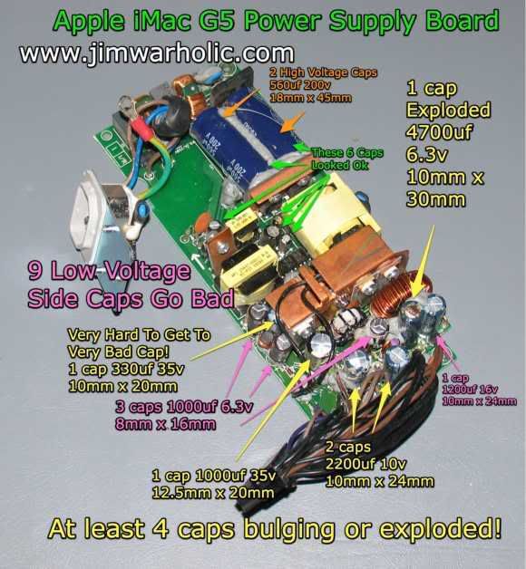
Figure #3
Here’s a confirmed list of the secondary (low voltage) side PSU capacitors installed in the iMac G5 17 inch model. It maybe different on the iMac G5 20 inch, ALS, and iSight models. Please send me an email confirmation or comment on the iSight models, iMac G5 20 inch models, and ALS (Automatic Light Sensor) models, along with any capacitor sizes, quantities, and values would be much appreciated. Please include the Apple p/n and the last four digits of the Apple EEE Code (The last four digits on the serial number). See Cap Note:
- 3x- 1000uf 6.3V 8mm x 16mm
- 2x- 2200uf 10V 10mm x 24mm
- 1x- 1200uf 16V 10mm x 24mm
- 1x- 4700uf 6.3V 10mm x 30mm
- 1x- 1000uf 35V 12.5mm x 20mm
- 1x- 330uf 35V 10mm x 20mm
What you are looking at in figure #3, once you remove the cover of the PSU, are signs of bad capacitors all over the printed circuit board. The first image (Figure #1) above shows the blown capacitor, burnt on the top, and burnt residue on the cover too. If you look closely at Figure #3 and Figure #4, you can see telltale signs of capacitors that are bulging and getting ready to blow their tops. Note the gray silicon rubber adhesive that has been squeezed into and between the electronic components on the circuit board. Some believe that this goop was used for anti-vibration and noise dampening as can be seen with the application of a small amount of goop on a potentiometer adjustment located in the top middle of the PCB, next to the transformers. I can understand the use of it to hold the large primary capacitors in place. However, in my opinion, I believe this was an attempt by the manufacturer (Apple) to make it more difficult to repair the PSUs when using it so liberally throughout the entire PSU. If however, I am wrong, and this is not the case, and the designer intended this goop to be used for anti-vibration noise dampening purposes, the assemblers seem to have gone overboard on their use of it, and it has had an unintended consequence of heat build up. If you look closely at the tall boy cap, I think this one ended up sandwiched in an oven, right next to the coil choke (see closeup picture on Figure #4). In my opinion, it’s not like the small capacitors are going to move once they are soldered in place. It’s also likely that this silicon rubber filler was instrumental in the early failure of the other capacitors too. Excessive heat buildup likely resulted from the insulating characteristics of silicon rubber encapsulation which would result in a runaway thermal chain reaction and cooked the components. Cool air circulation was none existent in these encapsulated areas of the PSU. This silicon adhesive must be gingerly picked at and cut away, in order to get proper access to all the bad capacitors, and be able to remove them when they are unsoldered from the PCB.
Directly below in Figure #4 is a slightly angled picture view, with a closeup of the capacitors on the iMac G5 Power Supply printed circuit board in view and most of the silicon rubber goop removed.
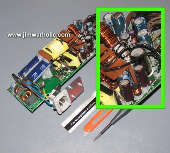
Click image for an even closer view of the PCB and PSU capacitors.
Figure #4
The tools I used on the PCB for cutting and picking away at the silicon adhesive are on display in Figure #4 too. I used by trusty precision miniature screwdriver (Husky model HD-74501 S “a gift”) with multiple bits in the handle, which came in handy for removing the torx fasteners and picking away at the small sections of silicon adhesive, the small retractable utility knife box cutter was used to cut away the big gobs of silicon rubber, and the inch/metric 6 inch scale was used for measuring the capacitor physical sizes.
So, the bottom line is most of the secondary low voltage side capacitors must be replaced on this particular G5 PSU. I will probably replace them all. Some of the capacitors I am told are difficult to find. This is especially true of some of the smaller diameter capacitors. Spaces are limited on the PCB. Also, note the one 350 microfarad 35 volt 10mm x 20mm capacitor (Figure #4 with close up view) that is located under the copper heat sink in the middle of the PCB. This is going to be most certainly problematic for capacitor replacement, since it is most likely that I will have to remove the 1000 microfarad cap in front of this 350uf capacitor in order to slide it out from underneath the heat sink assembly. The heat sink assembly is mounted to what appears to be voltage regulators that are impossible to remove without first removing other inductor choke coils, capacitors, and other components in front of the heat sink assembly.

Surface Mount Technology – SMT
Surface Mount Components – SMC
Surface Mount Devices – SMD
Figure #5
A word of caution about the bottom surface of the PCB before you proceed with on-board capacitor replacements. Be careful not to damage any of the SMC, Surface Mount Components (Figure #5 pictured on the right) located on the bottom of the printed circuit board. These discrete SMT, Surface Mount Technology micro components are very small (some of the SMD, Surface Mount Devices, are hard to see with the naked eye) and consist of SMC diodes, SMC resistors, SMC capacitors, SMC transistors, and SMC IC chips in close proximity to where the large electrolytic capacitor leads protrude through the bottom and are soldered to the plated through holes of the PCB. Be extremely careful when soldering next to these SMDs. If you heat up a SMD by accident with the soldering iron, (see lead-free soldering tips for more soldering information) you will potentially dislodge it from its PCB pad. Figure #3 shows the PCB top side surface before picture, with all the silicon rubber adhesive stuck between the electronic components. Figure #4 picture is after the silicon rubber, for the most part, has been removed from the components on the secondary side of the PSU.
Now, the next step in the process is to purchase the nine electrolytic, radial leads, low ESR capacitors designed for tight spaces. For most folks out there in Internet land, I realize there probably is much technical information to digest here in one quick reading. I feel like I have written and photographed a technical documentary. I will most likely publish an updated technical article or add to this document when I locate new capacitors and proceed with the the installation of these new low ESR electrolytic capacitors. Cap Note: I suspect I will have some different suggested sizes to use for cap substitutes. You are free to print out this document using the “print button” for your personal use, but you are not granted permission to distribute or publish it anywhere else without my prior approval. That goes ditto for all the articles published on this website too.
All information provided here is for instructional purposes only. Please note that I cannot be held responsible for any damage that you might do to your computer or yourself. This website is for educational purposes only and you are responsible for everything you do with the given information. You are responsible for the health and welfare of your own body and computer.
I hope this iMac repair training course series of articles helps everyone that is facing a decision of possibly having to go to the precious and non-ferrous metal reclamation and computer electronics recycle center with their crippled or broken down Apple iMac now and in the future. After all, I believe that these Apple G5 iMacs are not an EWaste product, and are most precious and beautiful machines for their owners to use. I think there is a lot of life left in these very powerful iMac G5 computer machines for today and tomorrow. At least I have a documented road map and general circuit diagram schematic of the main power supply components, along with engineering failure analysis that I will be using myself for technical reference for now and in the future. By-the-way, I now have a large quantity of high quality, low ESR, electrolytic capacitors available for sale for the DIY Apple iMac G5 motherboard repairs. See motherboard repair posting for quantities required. Or, you can order directly from my online store at Out West Sales today.
Power Supply iMac 20 Inch Model Apple Part Number — Apple p/n: 614-0326
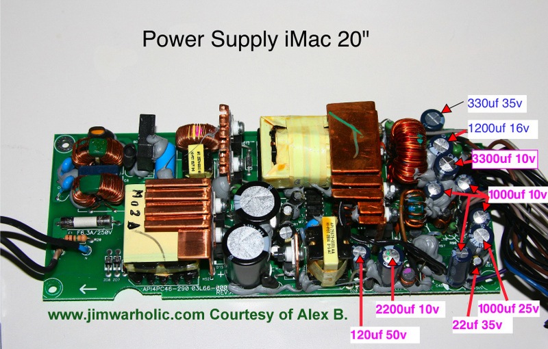
Capacitor List and Diameter Sizes For Power Supply Apple iMac 20 Inch
- 330uf 35v 10mm
- 1200uf 16v 10mm
- 3300uf 10v 10mm
- 2200uf 10v 10mm
- 1000uf 25v 10mm
- 1000uf 10v 8mm
- 120uf 50v 8mm
This particular power supply is (Apple p/n: 614-0326)
Note: According to Alex, capacitors would not exceed 32mm length. But also note that the cable wiring comes over the top of some of those capacitors on the right front section of the PSU. If the capacitors are too high, the wiring will not clear the PSU cover.
“Jim – do you have a pic of a 20″ iMac G5 power supply guts? Mine had the bulging/leaking capacitors. I removed them but need 2 reinstall and lost my notes as to which went where. On the top right hand side area is where they go.
I need to know where each size goes back. They are as follows: 1200mF 16V, 3300mF 10V, 2200mF 10V and 1000mF 10V any help is greatly appreciated.”
Additionally, if anyone finds a source available for engineering prints, technical drawings, or electronic schematics for Apple iMacs, please send me an email notice or send attachments to James. James is my clickable email address located on the right side of the website, just above “Chat with Jim Warholic” when I’m available online. I and others would really appreciate the circuit board schematics if you have them. Thank you, Jim Warholic
There is another option worth exploring for the Apple iMac G5 Power Supply. The option is to possibly convert a standard PC ATX power supply and use it for the Apple iMac. Wiring changes on the P1 pin-outs have to be made first. See the following note and image.
Accelerate Your Macintosh! News Page
iMac G5 Power Supply Connector Pin-Out (Voltages)
“I haven’t been able to find this anywhere using Google, so I took apart my iMac G5 (17-inch rev A) power supply and made a pin-out diagram.
-Chris N.”
Do not attempt the following if you do not know what you are doing. Severe damage could result. See note above concerning the information provided here. Compare the Apple iMac Pinouts diagram with that of the ATX Power Supply Pinouts Diagram. Pin modifications need to take place before plugging it in. Note also, there is a 24 Volts output on the Apple iMac Pinout diagram that is missing on the ATX Power Supply Pinout diagram. However, based on a thread in an online Apple Forum at InsanelyMac, titled iMac G5 Power Supply Question, a person as recently as January 2008 modified an ATX power supply and didn’t use the 24V, but I think he used an external monitor, and the iMac worked with this setup. Some folks indicate that the +24V is used for the internal backlit display. See quotes: “+24V is used to power the LCD inverter” and “24VDC line looks to be for the display (backlighting)”. Read full quotes in context at InsanelyMac Forum.
With that iMac G5 mod in mind, maybe someone can come up with an external power supply box, and just plug it in to the iMac P1 plug on the motherboard. Another person also emailed me in October of 2008 and mentioned he had this ATX power supply working for an Apple iMac g5 too.
This was recently posted as a comment by another person for the pin outs and voltage information: Note, I have confirmed this pin out information. Update: The various pinouts have been confirmed by at least one other customer also. Click the how-to link for more details about how to measure the iMac G5 power supply voltages and turn on the PSU when the PSU is removed from the iMac computer.
My 20″ iMac Power Supply connector – P-1
1. +3.3 – BlackA3B 12. +3.3 – BlackA3B 2. +3.3 – BlackA3B 13. +12v – BrownA3B 3. GND – BlackB4B 14. GND – BlackC4B 4. +5v Gray/PurpleA4B 15. On/Off – Gray 5. GND – BlackB4B 16. GND – BlackC4B 6. +5v Gray/PurpleA4B 17. GND – BlackC4B 7. GND – BlackB4B 18. GND – BlackC4B 8. PG – Blue 19. +12v – BrownA3B 9. +5.1Vsb – Purple 20. +5v Gray/PurpleA4B 10. +12v – BrownA3B 21. +5v Gray/PurpleA4B 11. GND 22. +20v – Brown FYI: More information for measuring the voltages can be found at my how to measure iMac G5 power supplies article. Be sure to read the article comments section for additional details.
Pin 22 supplies Panel voltage. Using a modified ATX Power supply (Need 12+ on pins 12 and 18), and the good 20 volts on the dead Apple Power Supply and a ground, I was able to boot my 20″ iMac using the combination of both power supplies. Someone else posted the pin out elsewhere on the web. I replaced just the domed capacitors on my power supply and still no luck. Can some of the capacitors be bad and not be domed? Can you check capacitors on the board without removal? Some go to infinite and stay, other go to infinite and fall back to zero when using an ohm meter?
A few points to consider when checking capacitors in the circuit and on the circuit board. It doesn’t always give the correct reading with a ohm meter whether using digital or analog meters because of other components affecting the readings of what you might be trying to check in the circuit. Yes, capacitors can be bad without physically looking bad. The electrolytic juice can dry up on the inside. And one more point that I would like to make, it sure would be nice to have a circuit board schematic for the power supplies in my hands. Feel free to send me one if you have it. Thanks.
For those looking for help to expand their business online, contact Professional Web Services today for a professional SEO and Internet marketing services company that will get your business found online at Google Search now.
Get your business website found online with Internet marketing services from Professional Web Services.
3/18/2009 Update: Installed new power supply in this iMac 17 inch G5 computer. Success! Installed keyboard and mouse too. Now I need new software for the white house.
A important note here is that I recommend only using “new” low ESR, long life, computer motherboard grade and switching power supply grade capacitors for all repairs. Do not use unknown surplus caps, or even new or surplus caps that have been sitting on the shelf for ages. My power supply was too far gone. It had something else blown in it.
I have the extra long life capacitors (rated at 10,000 hrs. on the large uf rated capacitors) and all are low ESR ratings for the power supplies, in stock now. Please take a look and compare these Apple iMac power supplies to your power supply before purchasing.
If your iMac power supply doesn’t look exactly as above, or would like to have a free consultation, and provide a visual evaluation for me to take a look at please send in your Apple iMac G5 pictures, to compare.
Get your B2B or B2C business website found online with Internet marketing services from Professional Web Services.